My Quantum Spin: Qubit Ordering and Operations
Software/Cloud Engineer and Architect specializing in AWS, Java, Angular, and Networking.
CCNA AWS Solutions Architect Professional AWS DevOps Engineer Professional
Overview
Picking up from Learning Quantum Computing, I continue chronicling my learning journey through quantum computing.
This post serves two purposes. First, I had a personal a-ha moment while manually working through the math to find the resulting statevector of a simple circuit. Namely, how to correctly and consistently compute tensor products of unitary matrices. Second, in association with that moment, I investigated the ramifications of how one may order the qubits in a circuit.
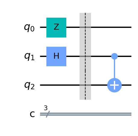
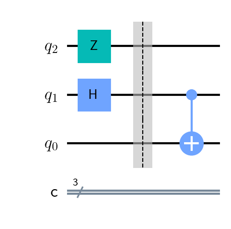
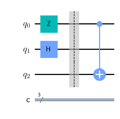
In this post, I will be working with the two similar but slightly different circuits shown here:
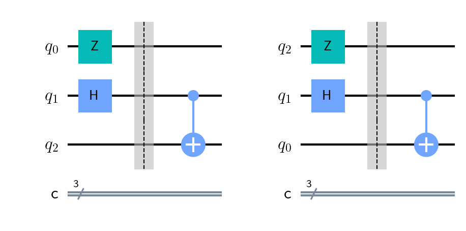
The difference resides in the order of the qubits. The first qubit, q0, is on top in the first diagram and on bottom in the second. Why is this important? In all of my learning resources, except one, the first qubit is on top. The exception insisted on putting it at the bottom. As a beginner, the situation bothered me. How could I reconcile this in my mind? Stay tuned.
First Circuit
Let's start by examining the first circuit. The circuit has no special significance (that I know of). It is simple enough to demonstrate what I learned.
As stated, it is the qubit order I see in most learning resources and diagramming tools: top to bottom. In this diagram, q0 is the first qubit, q1 is the second, and q2 is the third. I want to find the resulting statevector of this circuit. The correct answer depends on correctly defining the intermediate unitary operations.
I placed a barrier down the middle of the diagram to cleanly separate the operations. The operations before the barrier may be considered to be executed simultaneously. They consist of a Pauli-Z gate on q0, a Hadamard gate in q1, and no operation on q2. The "no operation" can be represented mathematically by an identity gate. To consider the effect of these simultaneous operations on the circuit we need to take a tensor (Kronecker) product of including Z, H, and I (the identity operation). One might go ahead and do this:
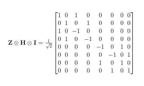
This will eventually lead to the wrong statevector. The correct product is:
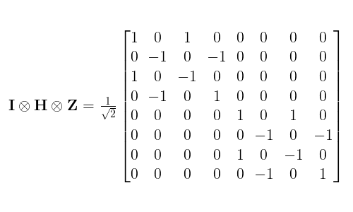
How do we keep this straight? Remember that the system's initial state is |000> where the rightmost digit represents the first qubit (q0). The order of arguments in the tensor product is the same from right to left. This was my a-ha moment.
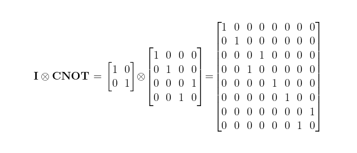
How about the effective operator to the right of the barrier? This time we have a multi-qubit operation, the CNOT gate. The operation on that side of the barrier is:
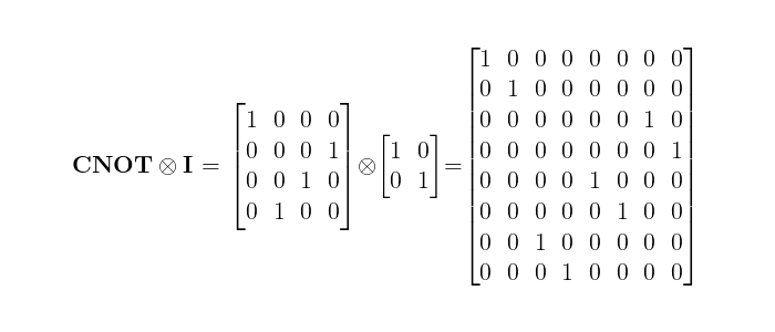
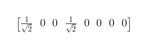
Based on the previous IHZ operation this seems to make sense, the operation on q0 is the identity matrix and it is the righthand argument. Following the math through from the initial state, we get a final statevector of:
This is the correct result. The result makes intuitive sense with the only possible states being |000> and |110>. Qubit q0 only had a phase flip and qubits q1 and q2 are entangled in a Bell state. All we had to do was remember the correct ordering of the operators.
Second Circuit
Things get interesting when we reverse the numbered order of the qubits:
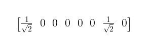
Now q0 is on the bottom. Again we start from the initial |000> state. Let's look at the resulting statevector first before we look at the math that gets us there:
There might be momentary shock due to the different result but again it is easy to see why this makes sense. The possible states of the system are |000> and |011. The first two qubits, q0 and q1, are in a Bell state while the third qubit q2 only experienced a phase flip. The result is different from the first circuit but consistent.
Evaluating the circuit, we start to the left of the barrier just as we did previously. This time, the ZHI tensor product is the correct operator:

Following the principle according to the ordering of qubits I discovered, we should expect the effective operator after the barrier to be:
This looks good but wait, that isn't the same CNOT matrix we used in the first circuit. Here are the two CNOT matrices used in the first and second circuits, respectively:
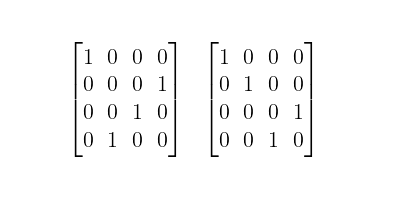
How am I going to remember which to use? The rule of thumb states that if the first qubit in CNOT is the control, use the first matrix. Otherwise, if the first qubit is the target, use the second matrix. Yuk. I wasn't satisfied. A formal mathematical derivation would be better. Moreover, what about the following situation?
The CNOT operator to be applied after the barrier now involves all three qubits! There is no tensor product to express the operator. Of course, we may imagine more complex situations with more qubits involved.
To answer my questions, I found the following Stack Exchange threads to be helpful:
Memorizing multi-qubit matrices will lead me astray. I need to formulate the correct matrix based on the situation.
Conclusion
Strictly speaking, a practitioner may rely on simulators to derive statevectors and the operators needed to achieve them. I always want to know why something works so doing the math is valuable. I hope this post was thought-provoking.